|
||||||||||||||||||||||||||||||||||||||||||||||||||||||||||
|---|---|---|---|---|---|---|---|---|---|---|---|---|---|---|---|---|---|---|---|---|---|---|---|---|---|---|---|---|---|---|---|---|---|---|---|---|---|---|---|---|---|---|---|---|---|---|---|---|---|---|---|---|---|---|---|---|---|---|
|
August 18, 1892 THE OTIS ELEVATING CABLE RAILWAY. Of modern cable inclines having steep grades throughout probably the longest is that running from the steamboat station Kehrsiten, on Lake Lucerne, to the summit of the Burgenstock in Switzerland, although this grade is exceeded on short inclines in this country, notably the Duquesne incline at Pittsburgh, Pa., which has an average grade of 58½%. The Burgenstock incline is 3,071 ft. long on the incline and 2,713 ft. long on the horizontal, with a rise of 1,444 feet. For the first 1,312 ft. from the bottom the grade is 32% and for the remainder of the line 57%, giving an average grade of 53% throughout. This line is also notable as being one of the only two inclines of any length, so far as we know, which use electric power generated by dynamos actuated by turbines to operate the cables. The power is supplied by two of Thury's dynamos operated by turbines situated about 1,400 ft. below the summit station, to which it is transmitted by copper wires and there reconverted into mechanical energy. The cable incline up the Monte San Salvatore, at Lugano, Italy, which was fully described in our issue of April 21, 1892, is the only other using electric motors to operate the cables. By far the longest cable inclines in the world are located in Italy. The older and better known of these is the line to the summit of Mt. Vesuvius, which is 10,500 ft. long. This line, however, is operated in two divisions, 6,900 ft. and 3,600 ft. long, respectively, the power house for both divisions being located at the Atrio del Cavallo at the end of the first division, where the passengers are also transferred from one line to the other. The other line ascends the Supurga, near Turin, Italy, on which is located the sepulchral chapel of the Italian royal family and is 10,243 ft. long. The grades on this line are comparatively low, the maximum being only 20%, and this for a short distance only. A very full description of this line was given in our issue of June 19, 1888. Aside from the Otis Elevating Ry. up the Catskills and the Lookout Mt. Incline in Tennessee, which was described in our issue of Jan. 7,1888, the most important cable inclines in this country are located at Pittsburgh, Pa., and Cincinnati, O. The first ever built are in San Francisco (Eng. News April 4, 1878; Nov. 10, 1883), but the inclines are neither very high nor very steep. There are quite a number of isolated plants in the Pennsylvania coal mining regions and in different localities. Such of the more important cable inclines as we have been able to collect details of in a hasty examination are given in the following table, to which we add details of the new Catskill Mountain line for comparison.
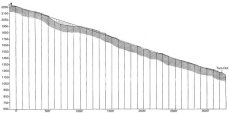
As compared with other incline railways to overcome mountain heights the Otis Elevating Ry. up the Catskills is in some respects a new departure. It starts from Otis Junction, on the Catskill Mountain Ry., and runs directly to the summit of South Mt., near the Catskill Mountain House. It is of the three rail type, the middle rail being common to both tracks, and one train ascends as the other descends. The trains pass each other about midway on the line where a fourth rail is introduced for a distance of about 100 ft., making a turnout. The total length of the line on the incline is 7,000 ft., and its total rise in that distance is 1,630 ft. A general profile of the line is given in Fig. 1. The maximum grade is 34%, and the average grade is about 12%. The gage of the track is 3 ft., the same as that of the Catskill Mountain Ry., with which it connects. OFFICIAL PROFILE OF THE OTIS ELEVATING CABLE RAILWAY UP THE CATSKILL MOUNTAINS
Surveys for the line were begun in December, 1891 The grading, earth and rock work were finished early this year. Beyond the large rock cuts and the natural difficulties of the ground there was nothing worthy of especial notice in this work.
The engine and boiler houses are located at the upper
end of the line, the latter being at one side of the track some 50 ft,
away from and below the level of the engine house. Steam is supplied
by two 150-HP. Manning patent vertical tubular boilers, each containing
152 tubes 15 ft. long and 2½ ins. in diameter, with a total heating
surface of 1,563 sq. ft. The total height of the boilers from the floor
line to the top of the bonnet is 22 ft. 10½ ins., and their diameter
at, the waist is 56 ins. The thickness of their shells is a
in. and of their heads v in. The
outside diameter of the furnaces is 73 ins., the inside diameter 66
ins., and the height 44 ins. The boilers were tested to 200 lbs., and
will be run under a pressure of 125 lbs. They were furnished by the
Q. N. Evans Construction Co., of New York city. In connection with the
boilers the same company furnished a smokestack 72 ft. high and 18 ins.
diameter. On a road of this kind the precautions taken to prevent accidents are of course especially important. In addition to the safety clutches on the cars, details and descriptions of which we defer until another issue, each of the engines is fitted with a strap or friction brake operated from the operating tower, as noted before. The main hoisting drum also has a strap brake which is to be connected with an automatic stop, to prevent the car from overrunning its proper position at the top of the incline The two terminal stations and each car are connected by electric gong signals. The rolling stock used on the line is very simple. It consists of four cars; two for passengers and two for baggage. Each train is made up of a passenger and baggage car. The passenger cars were furnished by Jackson & Sharp, of Wilmington, Del., and are 46 ft. long and 7 ft. 6 ins. wide, built on an angle of 10o 30'. They can seat comfortably 75 persons, and with crowding 90 persons. They weigh 22,000 lbs. each, and are provided with stationary seats said to be the counterparts of those used in the elevators of the Eiffel Tower. Each is mounted on two 4-wheel trucks provided with the ordinary hand brakes. The baggage cars are open, being simply platforms with sides and ends but no top. As before stated the road has been opened for regular operation, and runs trains in connection with the regular trains on the Catskill Mt. Ry., and the steamboat lines on the Hudson River. Its upper terminus is within a few rods of the Catskill Mountain House and from it the most popular, summer resorts of the mountains can be reached by a short drive, and in about four hours time from New York city. The ascent of the incline is made in about 10 minutes, or at the rate of about 700 ft. per minute. The road was built by the Otis Elevating Ry. Co., of which Mr. Chas. L. Rickerson is President, C. C. Hager, Secretary and Treasurer, and Chas. A. Beach, Superintendent. Its total cost was $275,000. The general contractor for its construction was Chas. L. Bucki, of New York, who sublet the grading to Pennell, O'hern & Co., of New York; the trestles, track-laying, buildings and timber work to Mairs & Lewis, of New York, and the machinery to Otis Bros. & Co., of New York. Otis Bros. & Co. again sublet the engines and hoisting machinery to the Walker Mfg. Co., of Cleveland, O., and the boilers to the Q. N. Evans Construction Co., of New York. The chief and designing engineer was Mr. Thos. E. Brown, M. Am. Soc. C. E., who designed the elevators for the West Shore R. R. at Weehawken, N. J. (Eng. News, Jan. 17, 1891). The assistant engineers were Mr. W. G. Howell, of Washington, D. C., and Mr. Gaylord Thompson and Mr. Chas. F. Parker, of New York, and the engineer for Mairs & Lewis was Geo. C. MacGregor. We are indebted to Mr. Brown and the two last named gentlemen for the details of the work given herewith. |
||||||||||||||||||||||||||||||||||||||||||||||||||||||||||
|
||||||||||||||||||||||||||||||||||||||||||||||||||||||||||
|
|